|
Electrical
System by pass.
This, I believe to be the most important item
to put at the top of the to do list for any LC owner. Here is a brief explanation
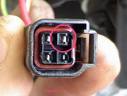
of what the Red Wire does in that connector assembly. It supplies all the
power to the electrical system When that little tiny connector (not whole
assembly Figure 1) fails you lose everything. You will not even get dash
lights, nothing zero. Got your Harley Hauler handy?
The Red wire in that plug assembly tapes into the main cable coming from
the battery. It is protected by the 30 amp blade fuse seen in figure 7.
Then it goes to the ignition switch, leaves the ignition switch as a
Orange wire and crosses around the bike to what looks like a relay. From
the relay (still Orange) it goes into the fuse box. This supplies all the
power to the fuse box. Hence, when it fails you have zero power to
anything.
Wes, my brother, had that fail on his bike while visiting Kathy and I. He
was four hundred miles from home, so not a real good thing. Wes has
documented this adventure so zip over to http://www.cableone.net/~waedens
for whole sad story. Which could very well have been your story.
Figure
3 and 4 show the by pass wire and fuse pre-assembled and soldered before
installation on the bike. This makes the modification much easier and
reduces the on bike soldering to one connection.
Figure
4 shows that I did break out the big soldering Iron. A 30 watt pencil type
will do nothing but piss you off and cause the whole project to take
longer. And you will not get a good solder joint.
Figure
6 show where I spliced into the bikes system at the connector's input. Effectively
causing a by pass should the tiny little contacts burn through. Which now,
they should not since there is an easy path fro the current to pass.
Figure
7 shows where the lug goes to tap the power from the battery.
Figure
8 shows I have put a round or two of tape as an added precaution to
prevent the fuse from coming out of holder. And for you 99 owner's, notice
the re-routing of the wiring harness. Compare to figure one and you will
see that in factory form, it just dangles to the outside of the relay and
computer. The 2001 models are already tucked nicely against the frame
tubes.
Perhaps
the area's I found rubbed places on the harness have developed into a
problem which caused the change on the 2001 models.
Good
luck, and you can now feel comfortable leaving the walking shoes at home.
Paul
|